Avoid the design mistakes that cost you time and material. These 5 tips help you get flawless custom waterjet cutting results on the first pass.
You’ve invested in the right material. Your client expects perfection. And your timeline doesn’t have room for do-overs.
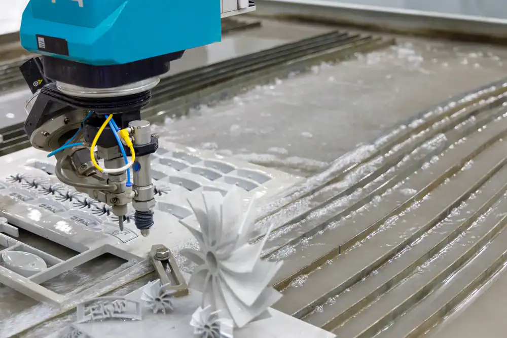
Custom waterjet cutting can deliver the precision you need—tolerances down to thousandths of an inch, zero heat distortion, and clean edges that go straight into installation. But here’s what most people don’t realize until it’s too late: the quality of your cut is determined long before the waterjet ever touches your material.
It starts with your design.
A poorly optimized CAD file, the wrong corner geometry, or a misunderstanding of how kerf width affects your dimensions can turn an expensive slab of marble or sheet of stainless steel into scrap. The good news? These mistakes are completely avoidable when you know what to look for.
Here are five design tips that make the difference between a flawless cut and a costly redo.
The waterjet follows your CAD file exactly. If your file has errors, your part will too.
Most cutting issues don’t come from the machine. They come from files that weren’t prepared correctly. Duplicate lines make the waterjet cut the same path twice. Open contours confuse the software about where to start and stop. Overlapping geometry creates unintended cuts that ruin your part.
Before you send a file for custom waterjet cutting, it needs to be clean. That means closed paths, no duplicates, and geometry that’s actually cuttable. If you’re designing in AutoCAD, SolidWorks, or Rhino, export as a DXF or DWG file. These formats preserve the dimensional accuracy that raster files like JPEGs or PNGs can’t.
Start by designing your part at actual size—1:1 scale in inches or millimeters. Not scaled to fit a sheet. Not in centimeters. The waterjet software reads your file exactly as drawn, and any scaling errors will show up in your finished part.
Next, check your file for common problems. Run a geometry check in your CAD software to find duplicate lines, open contours, and stray points. Use layer management to isolate your cut paths from reference lines, dimensions, or notes. The only geometry in your file should be what you want the waterjet to cut.
If you’re working in Adobe Illustrator or other design software, convert all text to outlines before exporting. Active text boxes won’t translate to cut paths. And if your design includes closed-loop letters like O, P, or D, add bridges to keep those inner sections connected. Otherwise, you’ll end up with letter-shaped holes instead of letters.
Avoid sending PDFs. They lose line accuracy and scale during export, which means your dimensions won’t be exact. Stick with vector formats like DXF, DWG, AI, or EPS. These maintain the precision you need for tight tolerances.
What makes a file actually cuttable versus one that creates problems? Cuttable files use lines and arcs, not splines or polylines. If your CAD program uses those entities, explode them to lines and arcs before exporting. Most waterjet systems can read lines and arcs directly, but splines require an extra conversion step that introduces potential errors.
One more thing: don’t dimension your drawing unless a specific feature needs tighter tolerances than the rest of the part. The waterjet follows the geometry, not the dimensions you’ve written on the page. Over-dimensioning just clutters the file and doesn’t change how the machine cuts.
When you take the time to prepare your file correctly, you eliminate the back-and-forth that delays projects. Clean files mean faster setup, fewer errors, and parts that come out right the first time. Regardless of if you’re cutting decorative metal panels, precision glass components, or intricate marble inlays, proper file prep is where perfection begins.
Let’s say you send a file with open contours. The waterjet software doesn’t know where the cut should end, so it either stops mid-path or connects points in ways you didn’t intend. Either way, your part doesn’t match your design.
Or maybe your file has duplicate lines you didn’t notice. The waterjet cuts the same path twice, which wastes time and can create a wider kerf than you planned for. On precision parts, that extra width throws off your tolerances.
Overlapping geometry is another common issue. When lines cross or overlap, the cutting software has to decide which path to follow. Sometimes it makes the wrong choice, and you end up with cuts in places you didn’t expect. On expensive materials like titanium, stainless steel, or marble, that’s not a mistake you can afford.
The worst part? You usually don’t discover these problems until after the cut is done. By then, you’ve already spent the material, the machine time, and the deadline buffer you were counting on. That’s why file review before cutting matters so much.
We review every file before cutting and flag obvious issues. But not all problems are obvious, especially if the file looks clean on screen but has hidden errors in the code. The more you understand about what makes a file cuttable, the less you rely on someone else catching your mistakes.
Think of file preparation like blueprints for a building. You wouldn’t start construction with incomplete drawings and hope the crew figures it out. The same logic applies here. A well-prepared CAD file is the foundation of a successful cut.
If you’re not sure whether your file is ready, ask. A quick review by someone who understands precision waterjet cutting can save you from expensive errors. It’s a lot easier to fix a file before cutting than to explain to your client why their custom architectural panel doesn’t fit or why their marble countertop has an unwanted gap.
Want live answers?
Connect with a Tri-State Waterjet expert for fast, friendly support.
Sharp internal corners slow everything down. And in some cases, they’re physically impossible to cut.
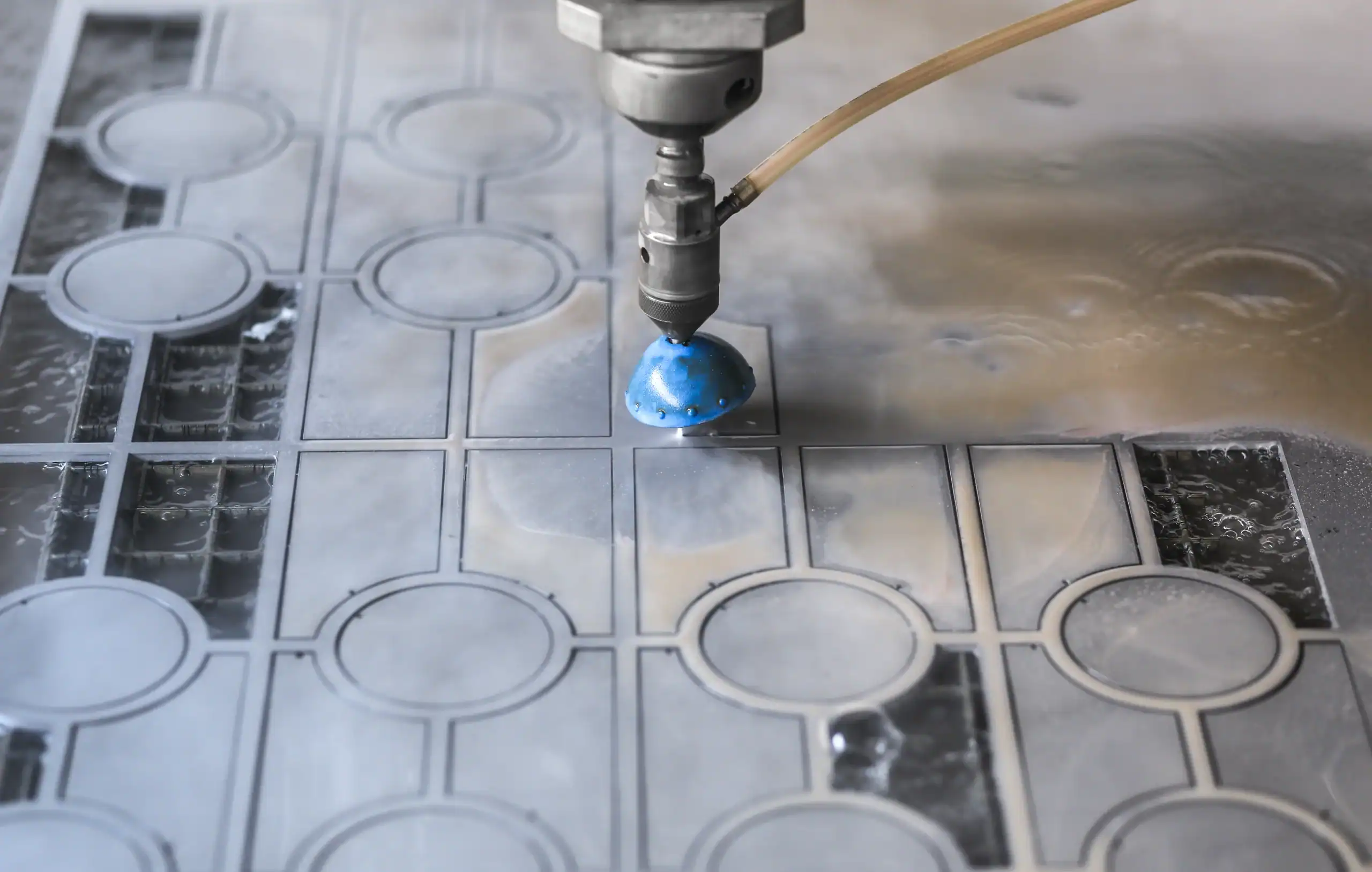
Here’s why: the waterjet stream has a width, called the kerf. That width is determined by the nozzle size, water pressure, and abrasive flow. Most precision waterjet cutting uses a kerf between 0.030 and 0.050 inches.
The stream can’t cut a corner sharper than its own radius. If your kerf is 0.030 inches, the stream radius is 0.015 inches. That means the tightest internal corner you can achieve is a 0.015-inch radius. If your design calls for a true 90-degree corner, the waterjet can’t deliver it.
Even when the waterjet can technically cut a sharp corner, it has to slow down dramatically to do it. Slowing down increases your cutting time, which increases your cost.
But there’s a bigger issue. When the waterjet decelerates for a sharp corner, the stream can lag behind the cutting head. This creates a phenomenon called stream lag, where the top of the cut is ahead of the bottom. If the software doesn’t compensate correctly, you end up with a corner that looks sharp on the top surface but rounded or misshapen on the bottom.
Thicker materials make this worse. The deeper the waterjet has to cut, the more the stream lags. On a 2-inch thick steel plate, the difference between the top and bottom of the cut can be significant enough to affect part fit. The same issue affects thick glass, marble, and composite materials.
The fix? Design with radii instead of sharp corners. A small fillet—even just 0.030 to 0.060 inches—lets the waterjet maintain a consistent speed without overcutting. Your parts come out faster, cleaner, and more accurate.
This applies to slots, notches, and any internal feature where two lines meet at an angle. Rounded ends on slots cut faster than square ends and eliminate the stress concentration that sharp corners create in the material itself. If you’re cutting metal parts that will be under load, those rounded corners also improve structural performance.
External corners are less of a problem. The waterjet can move past an external corner into the scrap material, allowing the lagging portion of the stream to catch up. Then it backs up to the corner and continues on the new path. This technique, called corner passing, produces sharp external corners without slowing down the cut.
But internal corners don’t have that luxury. There’s no scrap material to move into, so the waterjet has to decelerate, execute the corner, and accelerate back to cutting speed. Every sharp internal corner adds time and complexity to your cut.
If your design absolutely requires a sharp internal corner—say, for a part that mates with another component—talk to your waterjet operator about it upfront. Some shops can use taper compensation or 5-axis cutting heads to improve corner sharpness, but these techniques add cost and may not be available on all machines.
For most applications, a small radius is invisible to the end user and makes your part easier and cheaper to produce. It’s one of those design tweaks that costs you nothing but saves time and money on the back end.
Kerf width is the material the waterjet removes during cutting. If you’re cutting a 10-inch square and your kerf is 0.040 inches, the finished part won’t be exactly 10 inches. It’ll be slightly smaller because the waterjet removed material along the cut path.
Most waterjet software compensates for this automatically through a feature called tool offset or cutter compensation. The operator measures the actual kerf width before cutting and enters that value into the software. The machine then adjusts the cutting path so your finished part matches the dimensions in your CAD file.
But kerf width isn’t always consistent. It varies based on material type, thickness, cutting speed, and nozzle condition. A worn nozzle produces a wider kerf than a new one. Cutting thick steel creates a different kerf than cutting thin aluminum. Glass behaves differently than marble. Each material has its own characteristics.
If you’re designing parts with tight tolerances—say, components that need to fit together with minimal clearance—you need to account for kerf width in your design. That doesn’t mean adjusting your CAD dimensions. It means understanding that the waterjet will remove material along the cut path and communicating your tolerance requirements clearly.
For parts with internal holes or cutouts, the kerf works in your favor. The waterjet cuts from the outside in, so internal features end up slightly larger than drawn. For external dimensions, the opposite is true—the part ends up slightly smaller.
Most precision waterjet cutting can hold tolerances of ±0.003 to ±0.005 inches without special measures. If you need tighter than that—say, ±0.001 to ±0.002 inches—it’s possible, but it requires slower cutting speeds, test cuts, and careful machine calibration. That level of precision costs more and takes longer.
Add a small amount of clearance to your design when multiple pieces need to fit together. A 0.010-inch gap gives you room for kerf variation and makes assembly easier. Trying to design for zero clearance usually backfires because real-world tolerances don’t cooperate.
Also, keep your material thickness consistent across the part. Sudden changes in thickness—like a step or a pocket—affect how the waterjet behaves. The stream optimizes for a specific depth, and when that depth changes mid-cut, the kerf can widen or narrow. This throws off your dimensional accuracy.
If your design requires varying thickness, talk to your waterjet operator about it. They may need to adjust cutting parameters mid-job or program multiple passes at different speeds. Either way, it’s better to address it upfront than discover the problem after the cut.
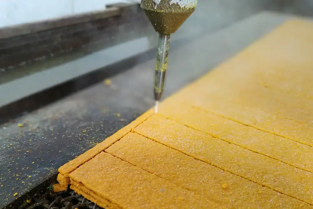
One more thing about kerf: it affects how tightly you can nest parts on a sheet. In processes like plasma cutting, the kerf can exceed 0.150 inches, which means you need large gaps between parts to prevent thermal crossover. Waterjet cutting has a much narrower kerf—typically 0.030 to 0.050 inches—so you can nest parts closer together. This reduces material waste and lowers your cost per part.
Smart nesting strategies can save significant money on sheet materials, especially when you’re cutting expensive metals, glass, or stone. If you’re not leveraging CAD-driven nesting software, you’re leaving both material and money on the table.
Design determines outcome. You can have the most advanced waterjet equipment in the world, but if your CAD file isn’t optimized, your parts won’t be either.
The five tips we’ve covered—clean file preparation, proper corner geometry, kerf width awareness, material-specific considerations, and clear communication with your operator—form the foundation of successful custom waterjet cutting. They’re not complicated. They just require attention to details that most people overlook until something goes wrong.
When you take the time to prepare your files correctly, design with the process in mind, and understand how waterjet cutting actually works, you get parts that fit perfectly the first time. No wasted material. No missed deadlines. No expensive do-overs.
If you’re working on a project on Long Island that demands precision cutting in metal, glass, marble, or any other material, we combine the expertise and equipment to turn your designs into flawless reality. From file review to finished parts, every step is built around getting it right the first time.
Summary:
Article details:
Share: